TESTING OF SHOTCRETE
Numerous tests have been devised for the purpose of determining the properties of shotcrete in the wet and hardened states. The following is a list of available test methods for the determination of these properties. Experience in regular use of each of these test methods increases the reliability of results. Australian Standard test methods must always be used where available. However, as appropriate Australian Standards do not exist for many of the properties commonly required for shotcrete, international standards can be used in these cases. When any of the following tests are required to be undertaken a NATA-accredited laboratory that is accredited to undertake the test in question should be used.
Slump
The slump of shotcrete is normally measured in the same way as for conventionally cast concrete in accordance with AS 1012.3.1. The test apparatus must be placed on level ground and moistened not to the point of excess water before use. The shotcrete is placed in the test apparatus, consisting of a frustum of a cone, in three layers of equal height and each layer rodded with a designated steel rod 25 times before the succeeding layer is placed. After the final layer is rodded the top surface of the shotcrete is struck off and the cone is lifted vertically from the shotcrete. The time for lifting the cone should be 3 +/- 1 second. The extent to which the shotcrete subsides below the height of the cone after the cone is completely removed is measured the average of which is the “slump” of the shotcrete.
Spread
An alternative to slump as a measure of consistency is the measurement of Slump flow according to AS 1012.3.5. This test is better suited to highly flowable mixes with a slump of greater than 200 mm. This test involves the filling of a slump cone, which is then lifted and the spread of the flowable concrete is assessed in terms of the diameter of the resulting pool on a flat spread table.
Flow table
The flow table test is similar to the spread test in that it involves measuring the diameter of a pool of concrete formed when it is released from a cone, but the EN 12350-5 flow table test differs in two ways from the AS 1012.3.5 test. Firstly, the cone is smaller so the amount of concrete involved in the test is reduced; and the flow table is raised and dropped 15 times to agitate the concrete and cause it to spread further than would occur solely in response to gravity.
Compressive Strength
The compressive strength of cast cylinders should be tested in accordance with AS 1012.9 using cylinder test specimens prepared in accordance with AS 1012.8. Cylinder test specimens are cast in two layers with each layer consolidated using a designated steel rod before the succeeding layer is cast. The upper free surface of the test cylinder should be screeded flat prior to covering with a lid to limit evaporation.
Specimens should not be disturbed during initial hardening. By convention, the strength of concrete at 28 days is normally taken to represent the long-term strength of this material. However, the 28-day strength may not be appropriate for all shotcreting applications. For example, if a certain minimum strength is required at a given early age, then strength should be measured at the same early age using an appropriate test method.
Methods of Measuring Early-Age Strength
Compressive Strength
Cast cylinders and cores are generally inappropriate to the measurement of compressive strength at ages earlier than 48 hours. Other methods of measuring the compressive strength of shotcrete by indirect means exist and should be used.
Measurement of early-age strength development is appropriate for assessment of the ability of shotcrete to support unstable ground and provides an indication of suitable re-entry times adjacent to freshly sprayed shotcrete. The most appropriate type of test to measure the early indirect-compressive strength up to 1 MPa is the Needle Penetrometer. The only effective means of assessing direct-compressive strength up to 8 MPa at early ages is the Beam-End Tester. The Soil Penetrometer provides an over-estimate of compressive strength, unless the results are corrected using the method by Bernard and Geltinger (2007) while the Hilti Gun requires a power-actuated tool operators’ certificate to operate.
Soil Penetrometer
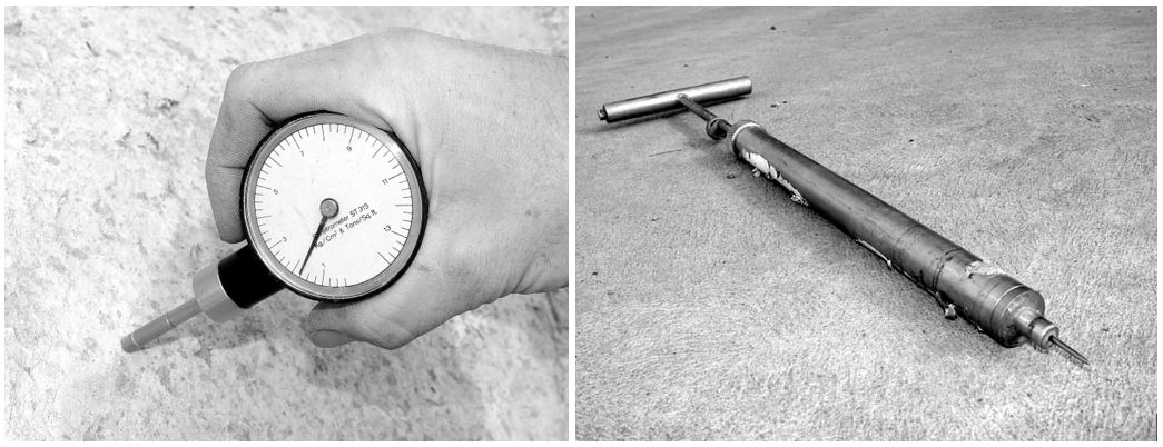
A soil penetrometer is a proprietary device consisting of a sprung flat-ended steel plunger calibrated to indicate the approximate compressive strength of the soil/concrete when forced into the surface a distance of about 6 mm. The device is used at approximately 6–10 locations across the surface of freshly-sprayed shotcrete at each age of testing, and readings are taken at 10–20 minute intervals until the required strength is achieved.
Although this test has the advantages that it is easy and inexpensive to perform, virtually non-destructive, and the test equipment can be readily carried around by operatives, an important disadvantage is that the device over-estimates compressive strength by a significant margin, and the results are strongly affected by the presence of aggregate and fibres.
Needle Penetrometers
The needle penetrometer consists of a 3 mm diameter steel needle at the end of a spring that is forced into the surface of setting concrete. The force required to drive the needle to a depth of 15 mm is used to determine the approximate compressive strength with the aid of a calibration chart. This method is suitable for determining compressive strengths up to 1.0 MPa. This type of needle penetrometer should not be confused with Vicat needle penetrometers and other types of needle penetrometers that are widely used to assess setting times for conventionally cast concrete.
Various types of electronic penetrometer are also available that rely on the same principle of correlating depth of penetration into a concrete surface with strength development. These are available with electronic load measurement and depth estimation to simplify the process of assessment.
Beam-End Tester
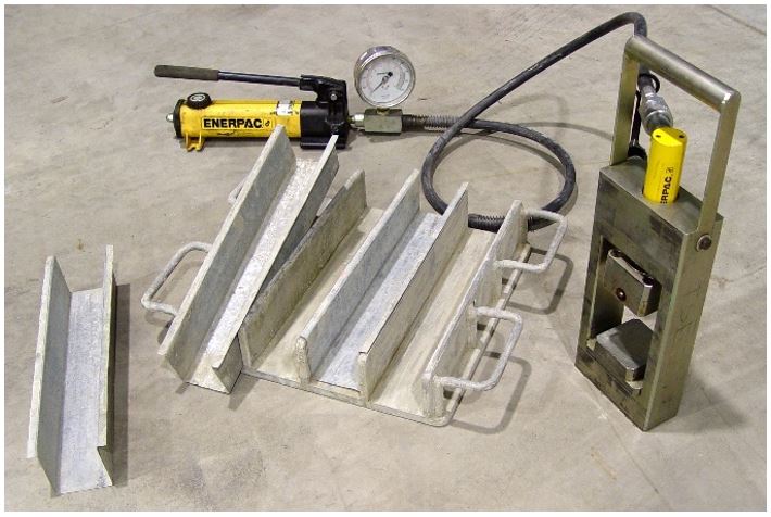 The ASTM C116-based beam-end tester (Morgan, 1999) is the only early-age strength testing device that involves direct compressive failure of concrete samples. Beams measuring 75 x 75 x 400 mm are produced by spraying shotcrete into an open-ended mould (other sizes can be used if desired). The absence of ends helps to prevent rebound getting caught inside the beam mould. After spraying and cutting back to size, the beams are left to harden and can be extracted from the mould and tested when the strength exceeds about 0.5 MPa (as measured using the needle penetrometer). Portions of the beams are subjected to direct compression between the platens of the test device and the compressive strength is worked out on the basis of the area of the platens. About 3–4 tests can be obtained using each beam.
Extracting the beams from the mould can be difficult at early ages, so use of pressed metal inserts are recommended. The metal inserts sit in the mould during spraying and are then removed with the beam inside. The fresh concrete beam remains in the pressed metal insert (made using approximately 0.5 mm-thick steel sheet) until it is time to test, whereupon the mould is “peeled off” the beam like a wrapping. In most cases, the beam survives this process without breaking, even if it is only 20–30 minutes old.
Hilti Gun-Test Method
This method is suitable for shotcrete strengths between 2 and 18 MPa. A proprietary nail is shot into shotcrete using a Hilti DX 450 nail gun and the embedded length is recorded. A nut is screwed onto the protruding end of the nail and a pull tester is placed under the nut. As the nail is progressively extracted the maximum pull-load is recorded on the dial and converted into compressive strength as a function of the embedded nail length. To obtain a reliable result it is recommended that at least 8 nails be used for each test age.
Flexural Strength of Plain Shotcrete
The flexural strength of plain shotcrete should be determined using beams sawn from panels or, for a base shotcrete mix, cast samples of shotcrete. If sprayed panels are not available then beams can be sawn from the in-place works but this is expensive, difficult, and normally not common practice. The preferred size of beam should be 100 x 100 x 350 mm or 150 x 150 x 600 mm extracted in accordance with ASTM C-1140 and tested in accordance with AS 1012.11.
If the flexural strength of fibre-reinforced shotcrete is required, beams measuring 100 x 100 x 350 mm or 150 x 150 x 600 mm should be extracted in accordance with ASTM C-1140 and tested in accordance with EN 14561 or ASTM C-1609. Flexural strengths at first crack and in the post-crack range obtained using the EN 14651 beam tests are typically 15% higher than those obtained for a nominally identical FRS mixture tested using ASTM C1609. If the thickness of the in-place shotcrete is insufficient to allow 100-mm thick beams to be extracted, sawn beams measuring 75 x 125 x 600 mm can be cut from the works and tested in accordance with EN 14488-3.
Post-crack Performance Testing
The term “Toughness Testing” is used generically to refer to a wide range of potential test methods, with there being many different types of beam and panel tests from different countries to choose from. However, the term has most commonly been taken to denote energy absorption in either beam or panel based test methods, as opposed to residual strength measurement.
In Australia the most common post-crack performance test for quality control of fibre-reinforced shotcrete has become the ASTM C-1550 test using a 75 mm-thick x 800 mm-diameter round panel, or the EN 14651 notched beam test. These are the preferred test methods for post-crack performance testing in Australia. An alternative beam test is the ASTM C1609 third-point loaded beam test using either 100 x 100 x 350 mm or 150 x 150 x 600 mm specimens.
The principal advantage of panels is the superior repeatability of energy-based post-crack performance measures derived from these tests compared to beams. The typical level of within-batch population variability for energy absorption derived using ASTM C-1550 round panels is about 13% (Bernard, 2002). Beams are normally used when a direct estimate of the Modulus of Rupture and the residual flexural strength of fibre-reinforced shotcrete are required. EN 14651 beams have become the preferred beam test because post-crack performance is expressed as a function of maximum crack width, and the results are used in the fib Model Code 2010. The results generated using this test method display an average CoV of about 22–28%.
In choosing the most suitable test method to use for a project, the thickness of the specimen in comparison to the design thickness of the insitu lining should be considered. The appropriate test method should be selected by the engineer or geotechnical expert. Always use the latest version of these standards.
Round-Panel Test Method – ASTM C1550
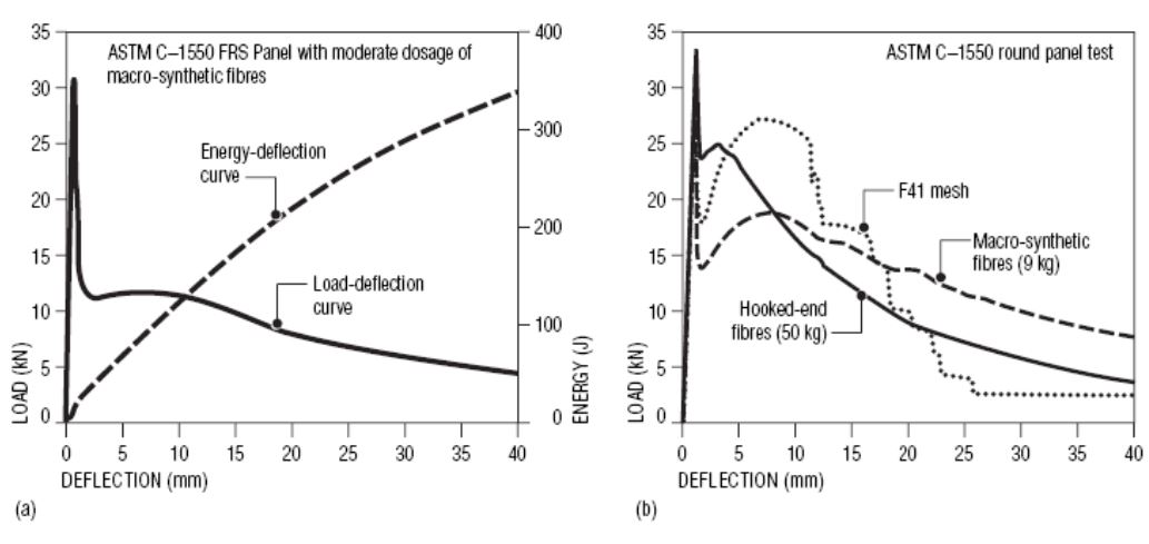
In this test method a 75 mm thick x 800 mm diameter round panel test specimen which is simply supported on three pivots symmetrically arranged around its circumference, is loaded at its centre. The energy absorbed up to a specified central deflection, or load resistance exhibited at a specified deflection, is taken to represent the ability of a fibre reinforced shotcrete to redistribute stress following cracking and therefore continue to offer structural support.
The minimum number of ASTM C-1550 round panels comprising a set of specimens is two. It is recommended that a minimum of three be produced in case one of the specimens is damaged prior to testing. Performance is calculated as the energy (measured in Joules) under the load-deflection curve but can also be expressed as residual strength.
Beam-Test Method – EN 14651
The EN 14651 notched beam has become more popular in recent years, partly because the results of this test are commonly used in design according to the fib Model Code 2010 and Eurocode 2, and partly because it is easier to conduct than ASTM C1609/C1609M beam tests.
A central point load is applied to a simply supported beam of 150 x 150 mm cross-section tested on a 500 mm span. A 25 mm deep notch is cut on the tensile face at the centre, ensuring that the crack occurs in this location. Performance is assessed in terms of crack width and load resistance, which can be converted into flexural strength using elastic engineering bending theory. A problem will occur if the FRS is deflection-hardening, because additional cracks may then arise outside of the notch. If this occurs, the test result is considered invalid. Moreover, the flexural strengths obtained using this test are always higher than results obtained using un-notched beams because of the way in which the crack propagates through the beam depth (Foster et al., 2013). The within-batch sample Coefficient of Variability is about 20–25% for residual flexural strength obtained using this test method.
Shotcrete beams tested according to any post-crack performance beam test shall not be sprayed as individual beams in moulds, they shall be cut from a much larger sprayed panel. However, a base shotcrete mix can be cast as part of initial laboratory trials.
Beam Test Method – ASTM C-1609/C1609M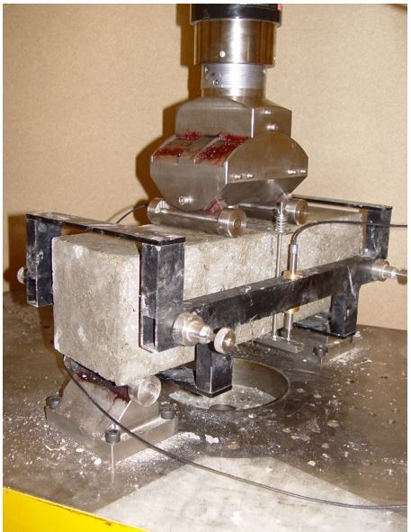
In this method a third-point loaded beam with dimensions of 100 x 100 x 350 mm (on a span of 300 mm) or 150 x 150 x 600 (on a span of 450 mm) is subjected to uni-axial bending. The load-deflection curve derived from this test can be used to determine the Modulus of Rupture representing the flexural strength of the concrete matrix and residual strengths or energy absorption representing the toughness of the fibre-reinforced shotcrete. The MOR and residual flexural strengths of a FRS mixture tested according to this method are normally about 15% lower in magnitude than for the same mixture tested according to EN 14651.
Beams are normally produced in sets of three or more; one set of specimens must comprise at least three beams. However, given the high degree of variation in post-crack performance for this type of specimen it is recommended that a minimum of 6 beams be tested in each set. Reported results are the first peak load and flexural strength, ultimate load and flexural strength and residual load and flexural strength values. Loads are reported in units of force (kN) and strength is reported in units of stress (MPa).
The rollers supporting the beam in this test method must comply with ASTM C1812, which ensures that a consistent Coefficient of Friction equal to 0.10 exists in the rollers. This helps to produce greater consistency in results between laboratories.
Double Punch Test
The double-punch test involves the imposition of opposing compressive forces (in the form of small round surfaces) to the ends of a cylinder or core. It was first developed by Chen in 1970. The compressive forces cause the cylinder to split into sectors, and steadily move apart in almost direct tension as the two opposing compressive disks move toward the centre of the cylinder. This test has been investigated as a means of obtaining direct tensile residual strength for FRS/FRC, and several different versions of the test method exist (including the so-called Barcelona test). This test method may be useful for obtaining a rough estimate of residual tensile strength of FRS obtained from cores, but there continue to exist problems in interpreting the results.
Density
The density of hardened shotcrete should be determined in accordance with AS 1012.12. The density of wet shotcrete should be determined in accordance with AS 1012.5. Shotcrete should never be sprayed into the sample vessel for this test, instead a sample of cast shotcrete should be used.
Drying Shrinkage
The unrestrained drying shrinkage of cast shotcrete specimens should be measured in accordance with AS 1012.13. The unrestrained drying shrinkage of cast shotcrete beams is related to the drying shrinkage suffered by in-place shotcrete on a rigid substrate but the relation between these two forms of shrinkage is complex and difficult to predict. Set accelerated shotcrete can be sprayed into the moulds used for AS 1012.13 but this is difficult and care should be taken to limit the amount of rebound incorporated into the specimens. Multiple extra specimens should be produced to allow for a high number of rejects.
When using AS 1012.13 to assess the drying shrinkage of shotcrete, it is recommended that the 7-day immersed curing period prior to shrinkage measurement be omitted as most in situ shotcrete does not enjoy the advantage of 7 days of wet curing. In practice, measurement of shrinkage over the first 24 hours after spraying is very difficult. For this reason, sprayed shotcrete specimens should be cured for 24 hours in a moist environment, after which they can stripped and drying shrinkage measurements can start.
Alternative restrained specimens similar to the type used in ASTM C1579 may be more applicable to shotcrete sprayed on a rigid substrate, as performance is assessed in terms of time-dependent crack width development over a central crack initiator. This is an area of performance assessment that requires improvement in the future.
Water Penetration through Bulk Shotcrete
Water penetration depth can be determined in accordance with EN 12390-8 (previously known as DIN 1048 Part 5). This test involves the extraction of a 100 mm or 150 mm diameter core of shotcrete which is sawn to reveal a flat face perpendicular to the direction of drilling. Water is applied under pressure to the flat-sawn surface for a period of 3 days after which the depth of water penetration is determined by breaking the core diametrically and applying “methyl blue” that reveals the penetration depth. Resistance to bulk water penetration can also be assessed using AS 1012.21 Boiled Absorption Test, as this is purported to be a measure of the degree of compaction in shotcrete. Similarly, the results of the RMS T362 Sorptivity Test are believed to represent the resistance of a mixture to water penetration at the surface and may be broadly related to compaction and permeability
 Bond Strength (Adhesion)
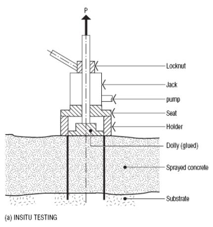
Adhesion is a very difficult property to measure. All the existing test methods involve proprietary equipment for the extraction of a core from in place shotcrete. The strength of adhesion between the shotcrete and the underlying substrate can be determined in accordance with Section 10.6 of the EFNARC European Specification for Sprayed Concrete.
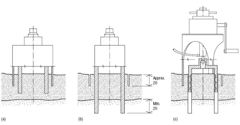
An alternative test, for the determination of adhesive strength, is Swedish Standard SS 137243. The EFNARC method involves extraction of a core in direct tension from a single core hole while the Swedish Standard 137243 method involves the generation of concentric core holes and use of an extraction device that ensures concentric loading. Debonding of shotcrete from the substrate can also be revealed by drumminess of the shotcrete lining in response to simple hammer soundings.
The Swedish Standard 137243 uses a similar method of producing the core, but a double-coring drill bit cuts two grooves with the inner core extending past the shotcrete into the substrate. A specially designed tension device (or epoxy-bonded rondelle) is then located over the inner core, with outer legs located in outer groove. The central core is then extracted and the peak-tensile load used to determine the bond strength. This method has the advantage that minimal moments are applied to the core during extraction, hence the result is more representative of the true bond strength of the shotcrete.
Determination of Fibre Content
There are two alternative methods of determining the fibre content of shotcrete: RMS B82 Method, and the EN 14488 Method. These methods are only applicable to the determination of fibre content for steel fibres and macro-synthetics; they are not appropriate for micro-synthetic fibres. Due to the small sample sizes used, both tests are highly unreliable as the fibre counts obtained have been found to be weakly related to both the dosage rate of fibres added to the concrete and the performance achieved.
RMS B82 Method
Determination of fibre content of wet shotcrete should be based on a wet sample taken from the mixer of a known volume not less than 6 litres. The sample should be washed and the fibre content separated, dried, and weighed with results reported to the nearest 2 grams. The result is reported as the weight of fibres per cubic metre of shotcrete. The results of this method are highly variable and it is recommended that a volume of concrete much greater than 6 litres be used.
EN14488 Fibre content of fibre reinforced concrete
Determination of fibre content of hardened shotcrete can be undertaken in accordance with Part 7 of EN 14488. This section involves two possible test methods: one involves the washing out of fibres from wet concrete, while the other involves extraction of cores from the shotcrete under investigation, determination of the volume of the cores, followed by crushing and separation of the fibres. The weight of fibres separated from the shotcrete is divided by the volume of the sample/cores to determine the dosage rate of fibres in kg/m3. The core-based method is subject to very high variability and is therefore only recommended when no alternative is available. Fibre counting can also be undertaken for cracked toughness specimens but the variability in counts is very high and the relation to performance is weak.
Fire Testing
Fire testing of shotcrete is a specialised area of performance assessment that is only relevant for pre-qualification of mixtures for high value infra-structure. Fire tests are normally undertaken on sprayed panels representing a portion of a tunnel lining. The tests are undertaken to ensure that the shotcrete can withstand fires of a selected intensity and do not suffer explosive spalling. In Australia, this is most commonly achieved by including micro-synthetic fibres and omitting quartz-rich coarse aggregates in the shotcrete mixture. However, for major tunnel projects, fire resistance must also be confirmed by testing.
Fire tests are conducted to various standards depending on the application. The higher the peak temperature, more rapid the rate of initial rise in temperature, and longer the duration of the test, the more difficult it generally is for FRS and other concrete materials to pass. Testing standards used in Australia include AS1530.4:2014 - Methods for Fire Tests on Building Materials, Components and Structures, and EFECTIS R0695:2020 – Fire Testing Procedure for Concrete Tunnel Linings and other Tunnel Components. Fire temperature curves used for transport tunnels in Australia typically follow either RABT or RWS Rijkwaterstaat specifications.
Many universities in Australia have the capacity to test small pieces of concrete at high temperatures, but only two laboratories have the capacity to test large panels to the specifications normally required for tunnel linings. These are the Structural Fire Testing Facility at Victoria University, Werribee, and the CSIRO Fire Laboratory at North Ryde, Sydney. Panels of representative shotcrete are typically prepared on the project site, shipped to the laboratory for several months curing, and then tested either in a loaded or unloaded state. Performance is quantified in terms of material lost during the test, or residual structural capacity following a test.


